Automating Your Drill Press
is making another thing easier in the shop
Watch the mists swirl while listening to dreamy music and allow yourself to be transported back in time to a point in our early history - I think Caveman - where there lived a woodworker named Ugg.
Ugg became interested in woodworking the minute he started banging on logs with his club and as he grew older, his entire purpose was to make the act of woodworking and using his tools more enjoyable. While Ugg foraged, he collected more tools and equipment and before long he found himself standing in a well-equipped cave.
One of the things he collected would eventually become known as the drill press.
Ever since that eventful day Ugg wondered why there couldn't be a better way to adjust the table's height without having to bend over and grope around like the other cavemen. Although Ugg thought there was a better way, he just didn't do anything about it because he had other things on his mind - like how to build a better Mammoth trap. And it came to pass that Ugg would leave it for someone else to work on and they left it and so did the next until many years of suffering and lamenting had passed.
Then along came Joe.
Now Joe, like Ugg, knew there had to be a better way, but he wasn't going to be like Ugg and leave it for someone else to work on. No, Sir. Joe wanted his cave to be more functional than Ugg's and we're going to read how he solved this ancient problem.
I seriously don't know how Ugg managed to carry on for so long but as far as I'm concerned, I classify the act of manually raising and lowering the table to be most annoying. I mean, pretend you're standing in front of the drill press with a hunk of wood in your hand and you know three things;
- the same bit is being used for the entire project
- the material you're using varies in width
- that for each different piece you must reach around to the rear of the table and turn a handle to crank it up or down
Sometimes you even have to hunker down to squint at the bit as you crank the table into position. Or, if your drill press is like mine, you can make matters worse if you have a nice big auxillary table installed to get in your way. Because now you have to run to the left side to loosen the clamp then run to the other side to work the crank then run back to the other side to tighten the clamp.
So, it may seem to you that Ugg's story sounds petty, maybe a wee bit fictional, but I have to side with Ugg on this one. With just a few spare parts and a couple hours of shop time, you can bring your drill press out of the caveman era and into the present by automating how you raise and lower the table.
The first thing you need to do is gather up the following list of components:
- A piece of plate aluminum 1/4" x 1' x 1' to act as the base.
- A suitable DC motor about 3 1/2" in diameter
- A DC controller
- 2 muffler clamps or U-bolts to fit the motor's diameter
- 2 sprockets
- A length of chain
- Some electrical wire
- 3 hex bolts 1/4"-20 x 1"
- A 1/4"-20 tap and a #7 drill bit
- Some 1/16" sheet aluminum
- Sheet metal screws or pop rivets
- 6 small wire nuts
- Several nylon wire ties
- A Double pole, Double throw switch
- A 120 volt LED indicator light (optional)
- Two 10-32 x 1/4" machine screw
I'll categorically state that the motor will be the hardest to find. This is because woodworkers don't usually go looking for DC motors. However, knowing where to look will make your task considerably easier.
The first place I'd recommend looking is at your local shopping mall - some inconsiderates refer to it as the landfill. Look for office machines or perhaps some piece of equipment thrown out from a hospital. Equipment used in hospital environments will almost always useDC motors; especially beds and tables. Certain equipment used in physical therapy may, too. If your local mall doesn't come through do a little poking around in junk shops and second hands stores. Don't ignore any local motor repair shops because they'll certainly locate one for you. As a last resort you can order them from such places as Graingers. Keep in mind that a DC motor requires a controller for it to operate properly. A controller is used to control the action of the motor; either up or down and fast or slow - be sure your controller can do both. So, when you find a DC motor simply follow the wires from it and you'll arrive to the controller. Although some AC motors are reversible, most cannot be speed controlled, however don't discount being able to use an AC motor. Just look for one that is small in diameter and not too high in RPM's.
For the sprockets it is important that you get two different diameters; use the large one on the table's mechanism - I used a 3" here. And, for the motor's shaft I used one that was an 1 1/2" in diameter. The reason for doing this is to decrease the eventual RPM of the table raising mechanism. Keep in mind that these sprockets are small and are meant to be used in small applications, therefore the holes that come pre-drilled in them will most probably be 1/2" so you may find yourself having to enlarge them to fit your applications.
Step One- Cutting the baseplate
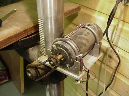
The base plate must be cut to the proper dimensions - take a look at the drawing below and then the above picture. The baseplate must encompass half the diameter of the support column in order for you to properly mount it to the table collar. Where you drill the holes for the mounting bolts is up to you, just must make sure you don't drill into the mechanism that moves the table.
The bandsaw is your best choice for cutting the baseplate - the blade will not be affected from cutting aluminum. If you don't have a bandsaw, then your next option is to use a jigsaw outfitted with a metal-cutting blade. You'll want to use a low speed setting to keep the aluminum fragments from filling the teeth on the blade.
It's important that the finished assembly remains as compact and tidy as possible, so cut your baseplate so that it is as wide as the motor and deep enough to take in the clamps plus half of the support column's diameter. This section is removed in order to bolt it on top of the collar mechanism.
Step Two- Drilling and tapping for the mounting bolts
The next procedure is to drill clearance holes in the baseplate and then the corresponding holes in the collar, these will have to be tapped. Unfortunately, this cannot be accomplished without first removing the collar from the support column.
-
Locate and loosen the clamp bolt of the table then remove it from the collar
-
Locate and loosen the two set screws on the head of your drill press.
-
Remove the head (it might be wise to have a helper here)
-
Crank the table up until it disengages from the rack and pinion track
-
Slide the collar all the way up until it can be removed from the column
Once the collar has been removed from the column take it to where you have a sturdy place to work.
-
Align the baseplate reasonably square to the collar, clamp securely
-
Mark the location of each hole on the baseplate with a center punch
-
Drill each location using an 1/8" drill bit
-
Switch bits to a 5/32" and repeat the drilling
-
Remove the baseplate from the collar
-
Switch bits to a 5/16" and repeat the drilling on the baseplate ONLY
-
Switch bits to a #7 and repeat the drilling on the collar
-
Tap each hole in the collar using a 1/4-20 tap
-
Bolt the baseplate onto the collar
Now, it's time for a trial fit - take the whole assembly back over to your drill press. You want to be sure that it will slide easily up and down the column without any restrictions. If there are any, file or sand the baseplate until everything is alright here then take the whole assembly back to where you were previously working.
Next we need to layout the holes for the clamps to hold the motor. I used muffler clamps because of the convenient flat spot they have, but I'm sure other methods will work just as well. When laying out the holes, be sure to elongate them, and make them 1/16" wider than the width of the bolts. This is important so you can have some adjustment once the motor is mounted to the baseplate.
The hard part is now complete!
Take the whole assembly back over to your drill press and put everything back together again. Once you've done this we can move on to installing the controller.
Step Three- Installing the controller
Before you continue with this step, and for your personal safety, I highly recommend that you read through the rest of this article for advice on seeking the assistance of a licensed electrician when dealing with electricty.
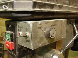
The chances of finding a controller with a perfect size case aren't very good, so you'll probably be faced with having to make your own box - like I had to do here.
The first phase in configuring your controller is to take a look at the wiring -all DC motors are reversible - and if your controller doesn't have one, you need to place a double pole, double throw (DPDT) switch into the circuit. The following schematic should help you to complete the switched circuit.
The wires that originally went from your controller to the motor are the same wires that will go to the middle connectors on your DPDT switch. The direction a DC motor turns is reversed when you reverse the DC current flow.
It may very well be that your controller won't be equipped with a knob for speed adjustment. If this is the case, don't set your hair on fire just yet. Somewhere on the card will be an electronic component that is adjustable - it may be labeled 'speed adj.' or something along those lines.
If you make your own case, be sure to isolate the circuit card from the box by using insulated spacers. If your motor doesn't go up when you throw the switch into the up position, simply reverse the wires labeled C1 and C2 at the switch.
To get incoming power to the controller box, I merely drilled a hole in the side of the drill press' head and tapped into the 'line in' at the switch. Doing it this way will minimize the number of wires plugged into an outlet and will still provide constant power to the controller. Drill and tap for two 10-32 screws so that you can mount the circuit box to the drill press head. |